The Problem of Multi-Functional Pins
Modern microcontrollers are becoming increasingly complex and more integrated devices. Their functionality grows every year. At the same time, manufacturers try to keep chip packages with a minimum number of pins. To resolve the contradiction between a large number of functions and a small number of pins, a system was devised that assigns multiple functions to a single pin. The specific function at any given moment is determined by the program.
In practice, the function for each pin is assigned during design and usually does not change during operation. This fact is reflected in the approach of StMicroelectronics in their proprietary software. I am referring to CubeIDE, where you can graphically assign specific functions to pins and configure settings for the peripheral devices associated with those pins.
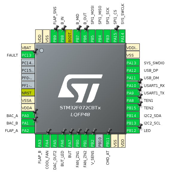
Two Approaches to Schematic Symbol Representation
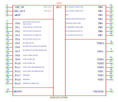
Such multifunctionality creates certain inconveniences for hardware designers. There are two main approaches. The first is complex: for each pin, the main function (which is set after a hardware reset of the microcontroller) is indicated, and next to it, a list of all possible alternate functions is provided. The disadvantages of this approach are that the list of alternate functions can be quite large and clutters the microcontroller's schematic symbol. Furthermore, it remains unclear which specific function is used in this project. And most importantly: developers are simply too lazy to list the full set of all possible functions for each pin.
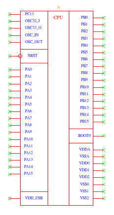
The second main approach to microcontroller schematic symbols is not to indicate additional functions at all. Only the main functions are specified. This approach is prevalent today. Creating schematic symbols using this principle takes significantly less time, but the main drawback remains completely: it is still unclear which specific alternate function is used in the project. This can be indirectly determined by the net name, however, the inconvenience for the hardware designer is obvious: he has to constantly switch between the pin assignment map and the schematic being designed.
The Original SalixEDA Solution
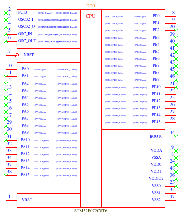
For SalixEDA, I use an original solution: I take the alternate function assignments from a specific software project. To implement this scheme, the schematic parameter functionality is used. The essence is that the schematic symbol of the microcontroller is created with the main pin functions, which are assigned after a hardware reset of the microcontroller. For each pin, parameters for alternate functions are also indicated nearby. These are essentially placeholders that will be replaced with the actual alternate functions directly in the schematic.
Import from CubeIDE
It works as follows. Insert the microcontroller into the schematic as usual. Select the microcontroller, right-click on it. In the menu that opens, choose "Selection Parameters" and you will see a dialog like this.
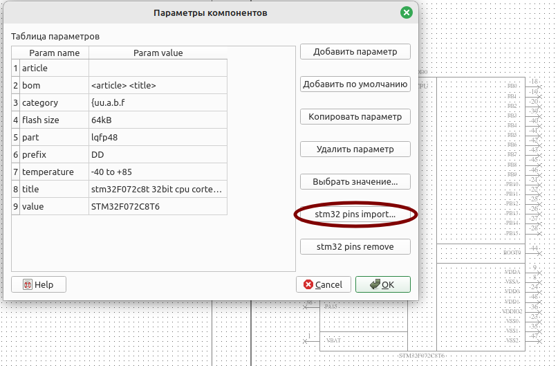
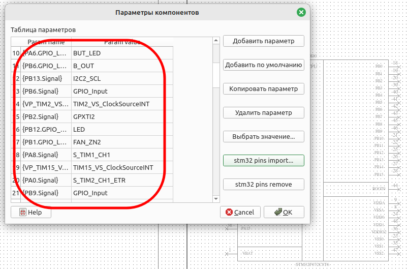
Click the pin import button and select the .ioc file of our project. In this file, the CubeIDE system stores the assignments of alternate functions to pins, as well as peripheral settings. SalixEDA scans this file and selects the entries related to the alternate functions of the pins. The result is a table like this.
Result on the Schematic
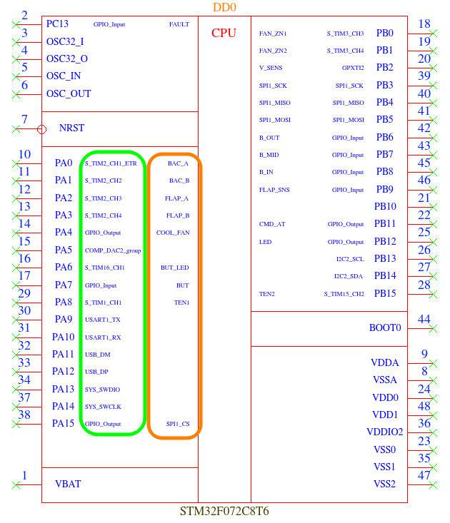
When you click the OK button in this dialog, the alternate functions of the pins, as well as the assigned names of these pins, are placed into the microcontroller's schematic symbol. In the following figure, the alternate functions of the microcontroller pins are highlighted in green, and the pin names assigned by the software developer are highlighted in orange.
Conclusion
Thus, SalixEDA solves the long-standing problem of multi-functional microcontroller pins by offering a third path: do not overload the schematic with a list of all alternate functions, but also do not hide them completely. The key feature of the approach is that the data is taken from a real software project, not entered manually. This guarantees the relevance and reliability of the displayed information.
As a result, the hardware designer sees on the schematic exactly those alternate functions that are actually used in the firmware, along with the assigned signal names agreed upon with the software developer. This completely eliminates the need to constantly check the pin assignment map and reduces the risk of errors during design.
Conclusion: The single source of truth (the .ioc file) now works for both the hardware designer and the programmer. Change the pin assignment in CubeIDE — update the parameters in SalixEDA with one click. No discrepancies between the schematic and the firmware.
Try this approach in your next STM32 project — you will see how much easier the collaboration between the hardware designer and the programmer becomes.